HC-SR04 Ultrasonic Range Sensor with Raspberry Pi
On our last post we looked at how to light a led using GPIO, and that was output. This time let's use a sensor and do some input. For this experiment I used a HC-SRO4 Ultrasonic Range Sensor and the sensor outputs 5V which needs to be dropped/converted to 3V3 so that it could be connected/used with GPIO without damaging our Raspberry Pi! Keeping all that in mind let’s go back to primary school Physics class along with Electronics in this experiment in order to explain each step in achieving today's goal!
Accessories required for this project:
- HC-SR04http://gadgets.mv/index.php?route=product/product&product_id=63
- 1kΩ Resistor & 2kΩ Resistorhttp://gadgets.mv/index.php?route=product/product&product_id=104
- Jumper Wireshttp://gadgets.mv/index.php?route=product/product&product_id=152
Ultrasonic Distance Sensor:
As the name indicates, ultrasonic sensors measure distance by sending a sound wave at a frequency above the range of human hearing. A basic ultrasonic sensor consists of one or more ultrasonic transmitters, a receiver and a control circuit.
The transmitter emits an ultrasonic wave which bounces off any nearby object and the receiver receives the wave reflected back from the target. The distance to the target is measured using the time lapses between sending and receiving of the ultrasonic pulse also known as the width of the pulse. This is possible because we know the sound’s velocity in the air. We will look into how we put all this in a formula later within the tutorial.

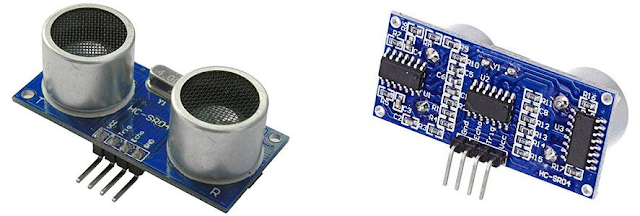
HC-SR04 has four pins that you need to worry about: VCC (Power), Trig (Trigger), Echo (Receive), and GND (Ground).
How does HC-SR04 work
VCC is the power supply for HC-SR04 Ultrasonic distance sensor which we will connect to one of the 5V pins from GPIO header of raspberry pi, ground it using GND, and we are going to use one of the GPIO pins to send an input signal to TRIG, which triggers the sensor to send pulse of at least 10 µS (10 microseconds). In response to that the sensor transmits a sonic burst of eight pulses at 40 KHz. This 8-pulse pattern makes the “ultrasonic signature” from the device unique, allowing the receiver to differentiate the transmitted pattern from the ambient ultrasonic noise.
The eight ultrasonic pulses travel through the air away from the transmitter. Meanwhile the Echo pin goes High (5V) to start forming the beginning of the echo-back signal. In case, If those pulses are not reflected back then the Echo signal will timeout after 38 mS (38 milliseconds) and return Low (0V). Thus a 38 mS pulse indicates no obstruction within the range of the sensor. If those pulses are reflected back the Echo pin goes low as soon as the signal is received. This produces a pulse whose width varies between 150 µS to 25 mS - depending upon the time it took for the signal to be received. The width of the received pulse is then used to calculate the distance to the reflected object. Lost me there? Even I do get lost with it, trying to explain this same scenario while struggling to put it in words. To keep it simple and for the ease of understanding let's look at a simple example.
Suppose we have an object in front of the sensor at an unknown distance and we received a pulse of width 300 µS on the Echo pin. We will use the good old formulae "distance = speed x time" from our physics book to calculate the distance of the object from the sensor.
Here, we have the value of Time i.e. 300 µs and we know the speed is 340 m/s. We have to convert the speed of sound into cm/µs in order to calculate the distance and that is 0.034 cm/µs.
Distance = 0.034 cm/µs x 300 µs
But this is not done! Remember that the pulse indicates the time it took for the signal to be sent out and reflected back so to get the distance we need to divide our result in half.
Distance = 5.1 cm
The above circuit and the simple equation from Kirchhoff’s Voltage Law that we studied at Physics class from primary school - can be applied in our calculations.

Without getting too deep into the math side, we only actually need to calculate one resistor value, as it’s the dividing ratio that’s important. We already know our input voltage which is 5V, and our required output voltage that is 3.3V, and we can use any combination of resistors to achieve the reduction. I happen to have a bunch of extra 1kΩ resistors laying around my table - meanwhile I wait for gadget.mv to send me their shipment “of stuff”, so I decided to use one of these in the circuit as R1. So my calculations were as bellow:

I definitely am not going to get a resistor of 1941Ω from Maldives on a normal day when it sunshine's or rains therefore I do need to tweak a bit here to get all this working, well isn't that a problem? If you remember from my last post I did also mention that in a case like this we can use the nearest higher available resistor, therefore we will be using a 1kΩ for R1 and a 2kΩ resistor as R2! Problem solved!!!
Assemble the Circuit
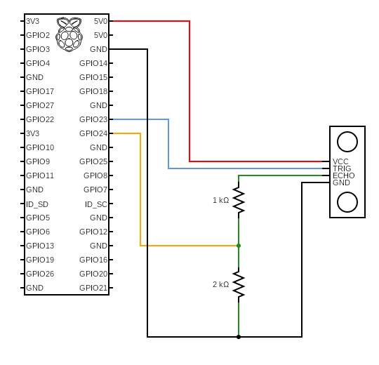
As mentioned earlier we will be using 4 pins from our GPIO header of Raspberry Pi for this circuit. Go ahead and connect the Vcc of your sensor into the positive rail of your breadboard, and plug GND of the sensor into your negative rail. Respectively from the GPIO header plug GPIO 5V (Pin 2) into the positive rail, and GPIO GND (Pin 6) into the negative rail.

And now connect TRIG into a blank rail, and plug that rail into GPIO 23 (Pin 16).

And then plug ECHO of the sensor into a blank rail, link another blank rail using R1 (1kΩ resistor). Link your R1 rail with the GND rail using R2 (2kΩ resistor). Leave a space between the two resistors. And finally Add GPIO 24 (Pin 18) to the rail with your R1 (1kΩ resistor). This GPIO pin needs to sit between R1 and R2

Well that is it! Our HC-SRO4 sensor is connected to Raspberry Pi. For a better understanding of the circuit refer to the schematic given below.
The Code
Well wait is that all? Don’t we have to do all those calculations using the distance formula and everything else that we had talked about earlier. Actually the library gpiozero handles all that for us at the backend, and this code gives great justification of what I also mentioned in my last post that gpiozero “requires minimal boilerplate code”. On the other hand if we had used RPi.GPIO we would have required to deal with all of those calculations manually. Ah! I just love using gpiozero so much, it keeps everything so clean and simple :-)
Now let's also look at what this code does. We started by importing DistanceSensor from gpiozero library and sleep from time.
sensor = DistanceSensor(echo=24, trigger=23)
And then we assign a variable (sensor) for the DistanceSensor - mentioning its echo and trigger pins. Even though on my source I have just only defined the parameters echo and trigger for the DistanceSensor it accepts a few more and below are the details for your perusal.
- echo (int or str) - The GPIO pin which the ECHO pin is connected to. See Pin Numbering for valid pin numbers. If this is None a GPIODeviceError will be raised.
- trigger (int or str)- The GPIO pin which the TRIG pin is connected to. See Pin Numbering for valid pin numbers. If this is None a GPIODeviceError will be raised.
- queue_len (int) - The length of the queue used to store values read from the sensor. This defaults to 30.
- max_distance (float) - The value attribute reports a normalized value between 0 (too close to measure) and 1 (maximum distance). This parameter specifies the maximum distance expected in meters. This defaults to 1.
- threshold_distance (float) - Defaults to 0.3. This is the distance (in meters) that will trigger the in_range and out_of_range events when crossed.
- partial (bool) - When False (the default), the object will not return a value for is_active until the internal queue has filled with values. Only set this to True if you require values immediately after object construction.
- pin_factory (Factory or None) - See API - Pins for more information (this is an advanced feature which most users can ignore).
After this we have an indefinite loop running printing the distance in centimeters (by default the distance returned by the library is in meters, therefore we multiply it by 100 to get the value in centimeters) while the script sleeps for 1 second between each print.
print('Distance to nearest object is', sensor.distance * 100 , 'cm')
sleep(1)

If you wish to check the source to see how the library does the calculation and the rest processes on the class DistanceSensor of gpiozero have a look at this. With that we will wrap up today's post! I will see you on a different one with more accessories to explore and learn through.
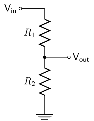
So, now we know that the object is 8.5 centimeters away from the sensor. Well all that is fine and now we have a great knowledge of how the sensor works, but there is a concern. Remember I said Echo remains low (0V) until a pulse is triggered and it goes High (5V). Also if you remember, in my previous post I even told you that once we introduce anything higher than 3V3 to GPIO it will harm the Raspberry Pi. To avoid this we will need to use a small voltage divider circuit, consisting of two resistors, to lower the sensor output voltage to something our Raspberry Pi can handle.
Voltage Dividers
A voltage divider is a simple circuit that can reduce voltage. It distributes the input voltage among the components of the circuit. That being said, the best example of a voltage divider is two resistors (R1 and R2) connected in series, with the input voltage (Vin) applied across the resistor pair and the output voltage (Vout) taken from a point between them. It is used to produce different voltage levels from a common voltage source but with the same current for all components in the series circuit. In our circuit, Vin will be ECHO, which needs to be decreased from 5V to our Vout of 3.3V.
This was a post I wrote for Baivaru Blog, here is the original post link:
https://blog.baivaru.net/hc-sr04-ultrasonic-range-sensor-on-the-raspberry-pi

