Mama I got a Raspberry Pi finally!
Introduction:
I am a kind of person who when interested in something, studies and learns as much as I can about that particular topic/thing until I am confident I have known enough of what is there to offer, perhaps that is how I got my nickname “The Scientist”. For quite awhile now, I have been eagerly waiting to get my hands on a Raspberry pi and finally I had the liberty of owning one - a week back.
The reason I decided to write about the experiments I did on Raspberry Pi and my case study notes is mostly just because I believe a huge part of studying is also putting the theory you learn in practical and documenting it. And also for the satisfaction of being able to explain and share a knowledge I have gained. After all there is a famous say which states something along the lines "Sharing knowledge ensures the entry of new".
Also do not be shy because Robert Mugabe also once said "No matter how bad you are, you are not useless. You can still be used as a Bad Example!"
What is a Raspberry Pi?
With that being said let’s briefly look at what a raspberry pi is. Raspberry Pi is a series of small single-board computers developed in the United Kingdom by the Raspberry Pi Foundation in association with Broadcom. Early on, the Raspberry Pi project leaned towards the promotion of teaching basic computer science in schools and in developing countries as a part of the charity which Raspberry Pi foundation was doing. Later, the original model became far more popular than anticipated, selling outside its target market for uses such as robotics just because it is the go-to microcomputer for all ages and abilities starting out in the wonderful world of programming and electronics.
There are five key models of the Raspberry Pi microcomputer on the market today - the Raspberry Pi 400, Raspberry Pi 4 Model B, the smaller Raspberry Pi Model 3 A+, their tiny sibling the Raspberry Pi Zero W and the brand new micro-controller Raspberry Pi Pico.
As I was getting my hands dirty with this small yet powerful microcomputer I was much more interested in learning everything about their bold claim of being able to use code to control real-world ‘things’ via the Raspberry Pi’s GPIO.
What exactly is a GPIO?
General purpose input-output (GPIO) on a Raspberry Pi are a set of 40 pins on newer models or otherwise 26 pins on older models. These pins are a physical interface between the Raspberry Pi and connected electronic circuits. In other words, you can think of them as switches that you can turn on or off (input) or that the Pi can turn on or off (output).
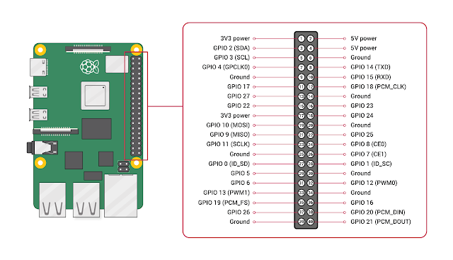
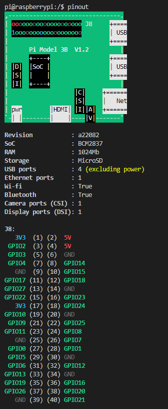
Any GPIO pins set as output/input can be set/read as high (3V3) or low (0V) respectively. This is something you should always remember since introducing any voltage higher than 3V3 or randomly plugging wires and power sources into your Pi can damage it. For this very reason it is always important to be aware of which pin is which and an easier way of having this reference from pi is by running the command “pinout” on the terminal(assuming you have Rasbian as your OS). Trust me I felt like a rocket scientist the day I found about it and that I did not have to google each time I needed the pin out structure.
As you have already guessed there are a number of programming languages and tools that can be used to control GPIO pins. I am specifically interested in programming/developing applications to use these pins with Python.
Developing for GPIO in Python
Before we jump on to the Python package that we are going to use, let me also explain my setup. To begin with I have a Raspberry Pi 3B V1.2 with Rasbian installed. I have also enabled SSH on the pi so that I can code remotely.
To enable SSH you could simply follow the below steps on terminal:
2. Select Interfacing Options
3. Navigate to and select SSH
4. Choose Yes
5. Select Ok
6. Choose Finish
On my coding terminal I am using VSCode with SSH FS extension installed. This extension allows "mounting" a remote folder (in this case our Pi) over SSH as a local Workspace folder.

GPIOZERO
GPIOZero is a wrapper around RPi.GPIO, which is a python library that allows people to control GPIO pins from their python programs. Authors of the library say gpiozero shares the same philosophy as PyGame Zero, which requires minimal boilerplate code to get started with. When they are confident in it, who are we to deny? Therefore, for most of it - we will be using gpiozero as this would keep our snippets clean, elegant and easy to read/understand.
Turning on an LED with your Raspberry Pi's GPIO Pins
I am going to do a series of posts under this same umbrella explaining projects I have done using several tools and sensors on raspberry pi. In each post I am going to explain the accessories, the reasons behind using them, schematics, the codes that I have used and most importantly from where I got the accessories. To begin with something simple we are going to light a led using raspberry pi.
Accessories required for this project:
Breadboard
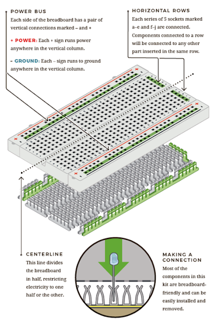
A breadboard is a solderless thin plastic board with holes used for temporary prototypes with electronics and test circuit designs. Most electronic components in electronic circuits can be interconnected by inserting their leads or terminals into the holes and then making connections through wires where appropriate. The breadboard has strips of metal underneath the board and connects the holes on the top of the board.
From where I got it:http://gadgets.mv/index.php?route=product/product&product_id=269
LED
A light-emitting diode (LED) is a semiconductor device that emits visible light when an electrical current passes through it. There are a handful of identifiers for finding the positive and negative pins on an LED. You can try to find the longer leg, which should indicate the positive, anode pin.
Or, if someone's trimmed the legs, try finding the flat edge on the LED's outer casing. The pin nearest the flat edge will be the negative, cathode pin.

LEDs will only work if power is supplied the correct way round (i.e. if the ‘polarity’ is correct). You will not break the LEDs if you connect them the wrong way round – they will just not light. If you find that they do not light in your circuit, it may be because they have been connected the wrong way round.
From where I got it:http://gadgets.mv/index.php?route=product/product&product_id=216
Resistor
An LED can only pass so much current before it will destroy itself. The maximum current varies by the LED's size and colour. On the other hand a Raspberry Pi can only supply a small current (about 60mA). The LEDs will want to draw more, and if allowed to, it can cause real harm to your Raspberry Pi, in fact even break it. Therefore putting the resistors in the circuit will ensure that only this small current will flow and the Raspberry Pi will not be damaged.

The maths to calculate the correct resistor value is fairly straight-forward, but in most cases the value you get out of your calculation won’t exactly match the available resistors in your hand. In such a case you can use the nearest higher available resistor, this is absolutely fine to do in almost all instances. If you do not want to do that you can also create your own resistor value using networks of other resistors, you’ll only ever want to do this out of curiosity!
From where I got it:http://gadgets.mv/index.php?route=product/product&product_id=104
Jumper Wires
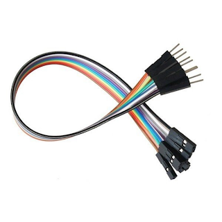
Jumper wires are simply wires that have connector pins at each end, allowing them to be used to connect two points to each other without soldering. Jumper wires are typically used with breadboards and other prototyping tools in order to make it easy to change a circuit as needed. Fairly simple. In fact, it doesn’t get much more basic than jumper wires.
From where I got it:http://gadgets.mv/index.php?route=product/product&product_id=152
Building the Circuit

I recommend that you turn your Raspberry Pi off for this part of this experiment, just in case you accidentally short something out. After all that is the best practice.
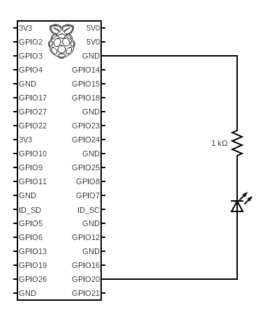
Here for this circuit we will be using one of the ‘ground’ (GND) pins to act like the ‘negative’ or 0 volt. Go ahead and connect a jumper wire from the 6th pin of the GPIO header of your raspberry pi to the rail, marked with blue, on the breadboard. Then connect the 1KΩ resistor from the same row on the breadboard to a column. Let me explain you why we use a 1KΩ resistor in this circuit with a simple calculation using ohms law (I am lazy so I used https://ohmslawcalculator.com/led-resistor-calculator). What we are looking for here is that the current through the led to be at an acceptable range for pi without causing it any damage yet light the LED, I explained why we should be worried about this earlier at the section of explaining what resistors are.

Now that we are sure it is safe, push the LEDs legs into the breadboard, where the cathode of the LED (long leg) is in the same column as the resistor we plugged in just now. The ‘positive’ end will be provided by a GPIO pin. Here we will be using pin 38 of the GPIO header which is GPIO 20 i.e. connect a jumper wire from pin 38 of GPIO header to the same column of bread board which has the anode of the LED (short leg).
Do not worry if you lost me for a bit there, for the ease of understanding and to have a look at everything I said above in a physical representation see the below schematics.
The Code
Explanation of The Code:
So, what is happening in the code? Let’s go through it:
The first two lines tell the Python interpreter (the thing that runs the Python code) the ‘libraries’ that our script will be using. A ‘library’ gives a programming language extra commands that can be used to do something different that it previously did not know how to do. This is like adding a new channel to your TV so you can watch something different. This process of “telling” is also known as importing. Here we are importing the time library so that we can pause the script later on and gpiozero that will tell the script how to work with the Raspberry Pi’s GPIO pins.
Here on this line we define a variable telling the script which GPIO pin of the Raspberry Pi our LEDs anode is connected to.
led.on()
time.sleep(1)
led.off()
time.sleep(1)
And then we have an indefinite loop running within which led.on() is where it turns the GPIO pin ‘on’. What this actually means is that the pin is made to provide power of 3.3volts. This is enough to turn the LED in our circuit on. time.sleep(1) pauses the Python program for 1 second and led.off() turns the GPIO pin ‘off’, meaning that the pin is no longer supplying any power.
This loop will run in a circle continuously until you press CTRL + C on your keyboard.
Conclusion
To wrap up what an achievement eh? When I got this working I felt more like Tony Stark from Iron Man. Well, either way that is not all. We have more to learn and in the next post we are going to dig and dive more into exploring with a few other accessories we have got. At this very moment I would also like to thank http://gadgets.mv/ for being the only partner whom I could trust in getting the accessories required for the value of money unlike many other shops out there in Maldives.

